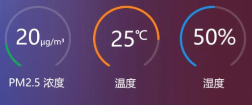
由于需要在网页中展示一个如下的效果:

项目开发采用的是React,使用 Ant Design 组件库,我发现Ant Design中有一个Progress很像,效果如下:
Process使用的是rc_progress,实现过程很巧妙,首先通过两个圆,然后将要显示进度的圆变成虚线,通过调节虚线起始位置来实现进度的变化。我也类似的做了一个仪表盘,对Process做了一些调整。
具体步骤如下:
首先画两个圆,一个为底图,一个为进度图。画法是分别左右画一个半圆。
1
2
3
| const pathString = `M 50,50 m 0,${radius}
a ${radius},${radius} 0 1 1 0,-${2 * radius}
a ${radius},${radius} 0 1 1 0,${2 * radius}`;
|
然后将底图的圆变成虚线,虚线中不显示的部分我开口的部分
1
2
3
4
5
6
| const len = Math.PI * 2 * radius;
const trailPathStyle = {
strokeDasharray: `${len - openWidth}px ${len}px`,
strokeDashoffset: `${openWidth / 2}px`,
transition: 'stroke-dashoffset 0.3s ease 0s, stroke 0.3s ease',
};
|
同样的方法,将进度圆也修改为虚线
1
2
3
4
5
| const strokePathStyle = {
strokeDasharray: `${percent / 100 * (len - openWidth)}px ${len}px`,
strokeDashoffset: `${openWidth / 2}px`,
transition: 'stroke-dashoffset 0.3s ease 0s, stroke 0.3s ease',
};
|
SVG部分代码如下:
1
2
3
4
5
6
7
8
9
10
11
12
13
14
15
16
17
18
19
20
21
22
23
24
25
| <svg
className={`${prefixCls}-circle ${className}`}
viewBox="0 0 100 100"
style={style}
{...restProps}
>
<path
className={`${prefixCls}-circle-trail`}
d={pathString}
stroke={trailColor}
strokeWidth={trailWidth || strokeWidth}
fillOpacity="0"
style={trailPathStyle}
/>
<path
className={`${prefixCls}-circle-path`}
d={pathString}
strokeLinecap={strokeLinecap}
stroke={strokeColor}
strokeWidth={strokeWidth}
fillOpacity="0"
ref={(path) => { this.path = path; }}
style={strokePathStyle}
/>
</svg>
|
修改完成后效果如下:
这部分代码我已经提交了一个建议给Ant Design,希望他们能做的更好。
后记,相关的SVG知识
<path> 标签:用来定义路径。
下面的命令可用于路径数据:
- M = moveto
- L = lineto
- H = horizontal lineto
- V = vertical lineto
- C = curveto
- S = smooth curveto
- Q = quadratic Belzier curve
- T = smooth quadratic Belzier curveto
- A = elliptical Arc
- Z = closepath
注释:以上所有命令均允许小写字母。大写表示绝对定位,小写表示相对定位。
stroke-dasharray 是用于设置虚线的属性。你可以使用它来设置每条划线长度以及划线之间空格的大小著作权归作者所有。
1
2
3
4
5
6
| <svg width="600px" height="300px">
<line x1="0" y1="20" x2="600" y2="20" stroke="#000" stroke-width="3" stroke-dasharray="10 2"/>
<line x1="0" y1="40" x2="600" y2="40" stroke="#000" stroke-width="3" stroke-dasharray="5 10"/>
<line x1="0" y1="60" x2="600" y2="60" stroke="#000" stroke-width="3" stroke-dasharray="1 1"/>
<line x1="0" y1="80" x2="600" y2="80" stroke="#000" stroke-width="3" stroke-dasharray="10"/>
</svg>
|
第一个值是划线的长度,第二个值是各个划线之间的空格大小。如果你只设置了一个值(如上面的最后一个示例),它会默认设置相同划线长度和划线空格。
stroke-dashoffset属性是设置虚线的偏移量。
1
2
3
4
5
6
7
| <svg width="600px">
<line x1="0" y1="20" x2="600" y2="20" stroke="#000" stroke-width="3"
stroke-dasharray="50 30"/>
<line x1="0" y1="40" x2="600" y2="40" stroke="#000" stroke-width="3"
stroke-dasharray="50 30"
stroke-dashoffset="10"/>
</svg>
|
第二条线设置stroke-dashoffset=10,线条偏移了10,效果如下:

